Welcome to ToupTek
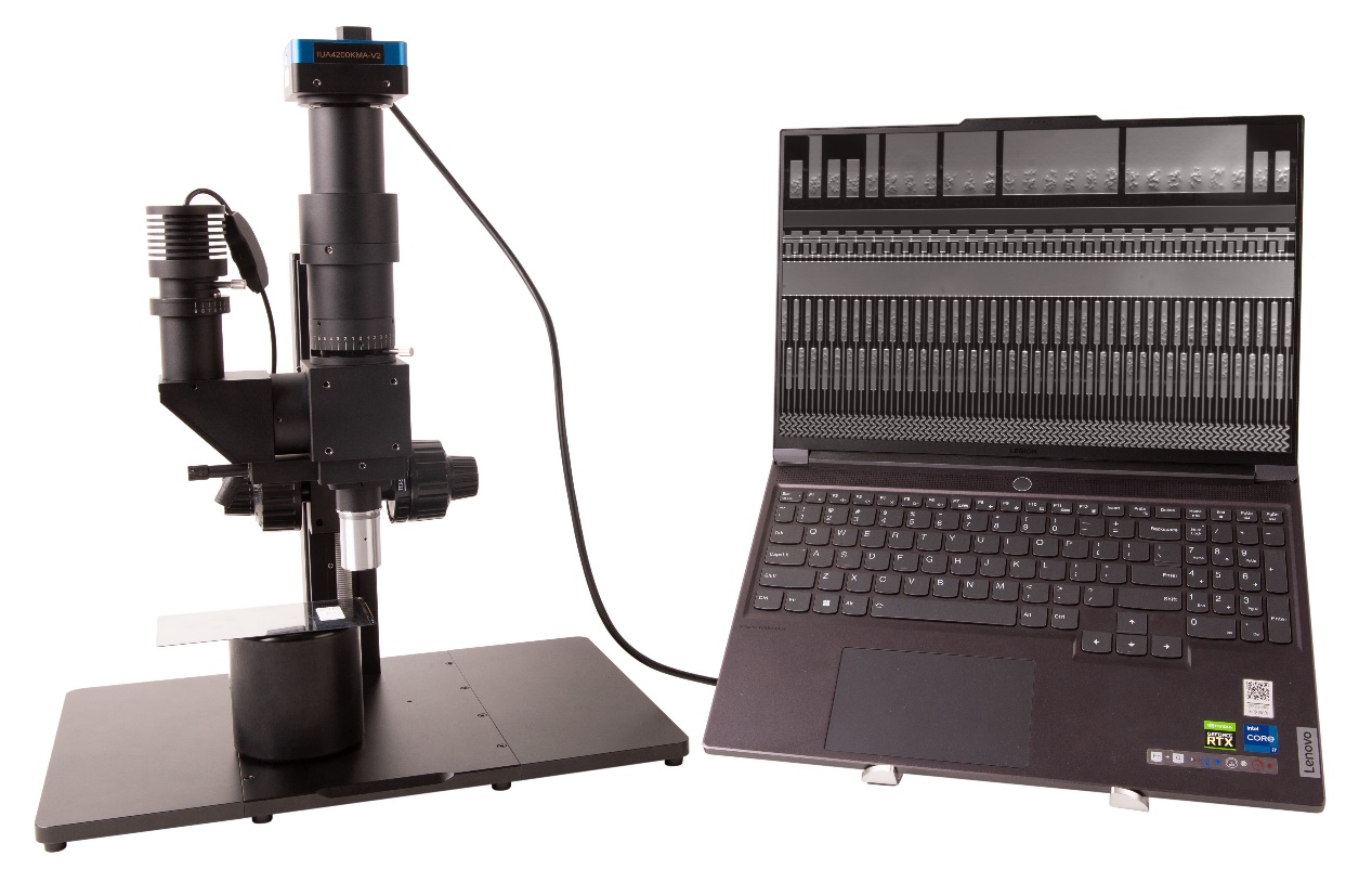
DIC (Differential Interference Contrast) microscopy system is designed with the principle of dual-beam polarization interference. The process is as follows:
1. After the linearly polarized light emitted from the polarizer passes through a Nomarski prism with birefringence properties, it is decomposed into two beams of polarized light that vibrate perpendicular to each other and have a certain phase difference;
2. After two incoherent beams of light are irradiated onto the sample, the slight unevenness or difference in refractive index on the surface of the sample in the field of view causes an optical path difference between the two beams of light. After being reflected by the sample, the two beams of light pass through the Nomarski prism and rejoin;
3. The merged light passes through the analyzer to make their vibration directions consistent and interfere;
4. The light and dark contrast of the sample details is enhanced due to the interference and amplitude changes of the light beam. At the same time, the sample detail image presents a three-dimensional relief-like effect.
The Nomarski prism can be adjusted horizontally, which acts like a phase-shifting compensator to change the brightness and interference color between the object and the background in the field of view, thereby achieving the ideal observation effect. Figure 1 is the DIC100 series differential interference microscope.
- Imaging light path: 1X (Tube lens focal length 180 mm), different magnification objective can be customized;
- Imaging light path image surface size: 25mm;
- Imaging light path spectral range: visible light;
- Camera interface: C/M42/M52, etc. optional;
- Lighting method: Critical illumination / Kohler illumination(optional);
- Lighting source: 10W white / blue LED (optional);
working distance objective lens parameters (45mm parfocal length)
|
Order code |
Magnification |
NA |
WD/mm |
Focal length(mm) |
Resolution(um) |
OFOV(mm) |
IFOV(mm) |
Thread |
|
DICL2.5XA |
2.5X |
0.075 |
6.2 |
8 0 |
4.46 |
10 |
25 |
M26*0.705 |
|
DICL5XA |
5X |
0.15 |
23.5 |
40 |
2.2 |
5 |
25 |
M26*0.705 |
|
DICL10XA |
10X |
0.30 |
22.8 |
20 |
1.1 |
2.5 |
25 |
M26*0.705 |
|
DICL20XA |
20X |
0.40 |
19.2 |
10 |
0.8 |
1.1 |
25 |
M26*0.705 |
|
DICL50XA |
50X |
0.55 |
11.0 |
4 |
0.6 |
0.44 |
25 |
M26*0.705 |
working distance objective lens parameters (60mm parfocal length)
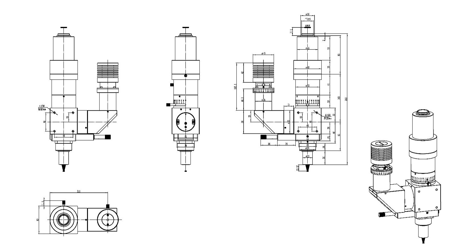
DIC100 Series Microscopy System Dimension
Conductive particle detection of LCD/OLED and other products
The number of conductive particles in the LCD circuit is the key to determining its conductive performance. Fewer conductive particles will reduce the conductive performance of the circuit and may cause display failures on the LCD screen; too many conductive particles will cause waste of raw materials. In addition, the presence of adhering conductive particles in the circuit will have a greater impact on particle counting, causing the calculated number of particles to be less than the actual number, affecting the accuracy of the detection results.
Figure 3 is an image of conductive particles on an LCD screen taken using a DIC microscope system; Figure 4 is an image of the same position on the LCD screen taken using a metallographic microscope system. In Figure 3 , the outline of the conductive particles is clearly visible, but in Figure 4 , the conductive particles cannot be observed by the metallographic microscope system.
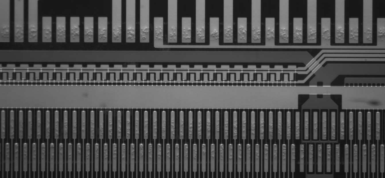
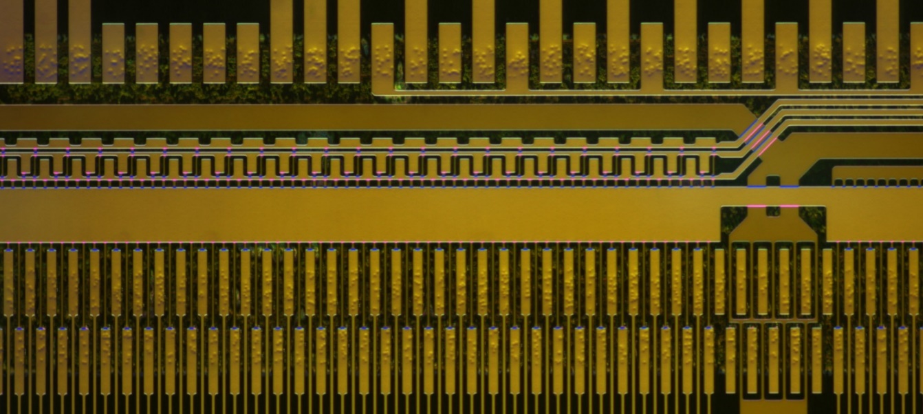
Figure 3 DIC100 series microscopy system shoots conductive particles on the LCD screen (top) blue LED lighting + black and white camera; (bottom) white LED lighting + color camera
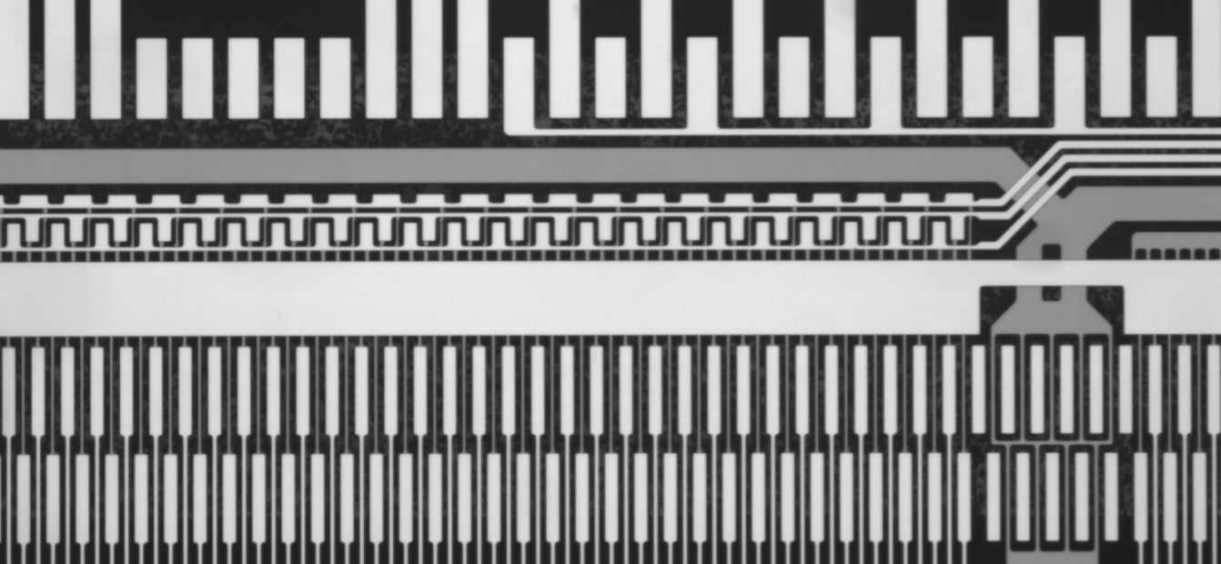
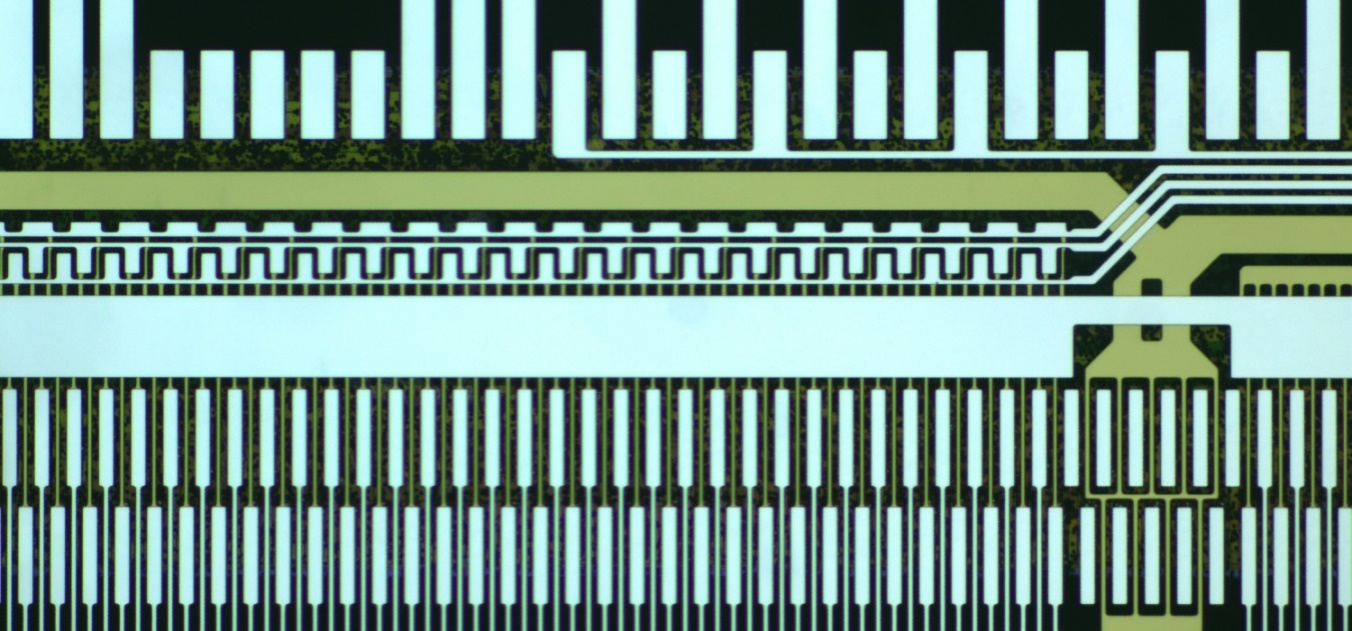
Figure 4 Metallographic microscope system captures LCD screen (top) blue LED lighting + black and white camera; (bottom) white LED lighting + color camera
Sample surface crack and defect detection
As one of the powerful detection and analysis methods in modern material metallographic examination, Differential Interference Contrast microscopy has many advantages, including relatively low requirements for sample preparation and an obvious sense of relief when observed under the microscope.
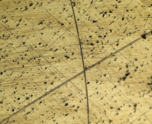

Figure 5 Real shot of metal surface (left) metallographic microscope system; (right) DIC100 series microscope system
Figure 5 shows details such as fine structures or defects that are invisible or barely visible in the incident light field with an ordinary metallographic microscope on the left, but can be easily observed using the DIC 100 Series Differential Interference Contrast microscope system on the right. In addition, the DIC100 series Differential Interference Contrast microscopy system can also observe the details of particles, holes, cracks and uneven contours in the sample, making material analysis more reliable.
Microbial cell detection
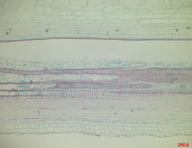
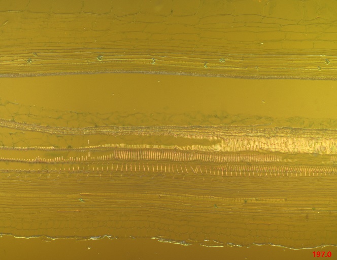
DIC 100 Series Differential Interference Contrast microscope system can conduct non-destructive detection of activity of living cells. According to the effect of optical staining, it can debug images with different interference colors; change the focal length to obtain clear images at different levels; with high resolution, it can clearly display the intracellular contours. structure. Figures 6 and 7 show the comparison results.
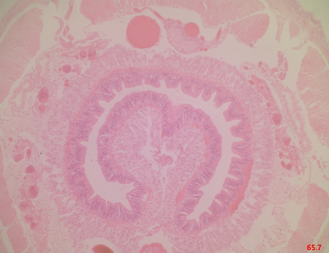
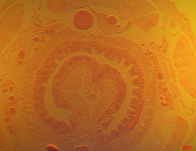
Figure 6 Real shot of Earthworm biological slices (left) biological microscope system; (right) DIC100 series microscope system

Order code
Magnification
NA
WD/mm
Focal length(mm)
Resolution(um)
OFOV(mm)
IFOV(mm)
Thread
DIC5XA
5X
0.15
20
3 6
2.23
5
25
M20*0.705
DIC10XA
10X
0.30
15
1 8
1.1
2.5
25
M20*0.705
DIC20XA
20X
0.40
10
9
0.75
1.25
25
M20*0.705
DIC50XA
50X
0.80
2.5
3.6
0.41
0.5
25
M20*0.705